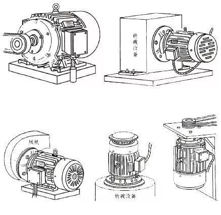
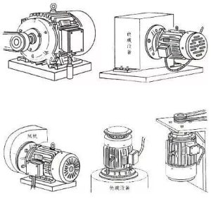
The way an electric motor is mounted (see diagram below) refers to how it is connected to the frame or other components in a mechanical system. There are two code forms, one is IMBx and the other is IMVy. Among them, IM is the internationally accepted installation method code; B represents horizontal type, which is limited to the motor axis being horizontal; V represents vertical type, which is limited to the motor axis being vertical; x and y are each 1 to 2 numbers, indicating the connection location and direction.
Motor installation type code
IM+B (or V)+Arabic numerals (1-2 digits)
IM: The abbreviation of “Installation al Mounting type” in English;
B: Indicates that the motor is installed horizontally when in use, with the shaft in the horizontal direction;
V: Indicates that the motor is installed vertically when in use, with the axis perpendicular to the horizontal direction.
Note: The main shaft extension end of the motor is uniformly defined as the “D” end. If it is a double-shaft extension motor, the auxiliary shaft extension end is uniformly defined as the “N” end.
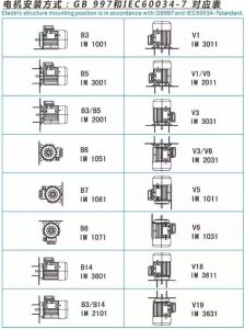
IMB installation code explanation
B3——Horizontal type installed on foundation components with footings;
B35——Horizontal borrowed foot is installed on the basic component, and is attached with flange installation;
B5——Horizontal flange installation;
B6 – horizontal type installed on the wall with feet, the feet are on the left when viewed from the D end;
B7 – horizontal type installed on the wall with feet, the feet are on the right when viewed from the D end;
B8 – Horizontal type installed on the top with feet;
B9——Horizontal D-end without end cover is installed on the end face of the D-end machine base;
B15——The horizontal type adopts the main installation on the foundation, and the D-end without end cover adopts the auxiliary installation on the end of the machine base;
B20——Horizontal type has raised feet and is installed on the basic components with the feet.
Rule: There are no auxiliary or additional installations with only one numerical code.
IMV installation code explanation
V1——Vertical installation with flange, D end facing down;
V15 – vertical installation on the wall with feet and flange for additional installation, with the D end facing downward;
V3 – Vertical installation with flange, D end facing up;
V5——Vertical installation on the wall with feet, D end facing down;
V6 – vertical installation on the wall with feet, D end facing up;
V8——Vertical D-end without end cover, installed on the end face of D-end machine base, with D-end facing down;
V9——Vertical D-end without end cover, installed on the end face of D-end machine base, with D-end facing up;
V10 – The vertical base has a flange and is installed with the D end facing downward;
V16 – The vertical base has a flange and is installed with the D end facing up;
The above codes are only for the installation methods of motors and basic components, and other codes are used for the connection methods with equipment.